 Download:
Figures of the Article
-
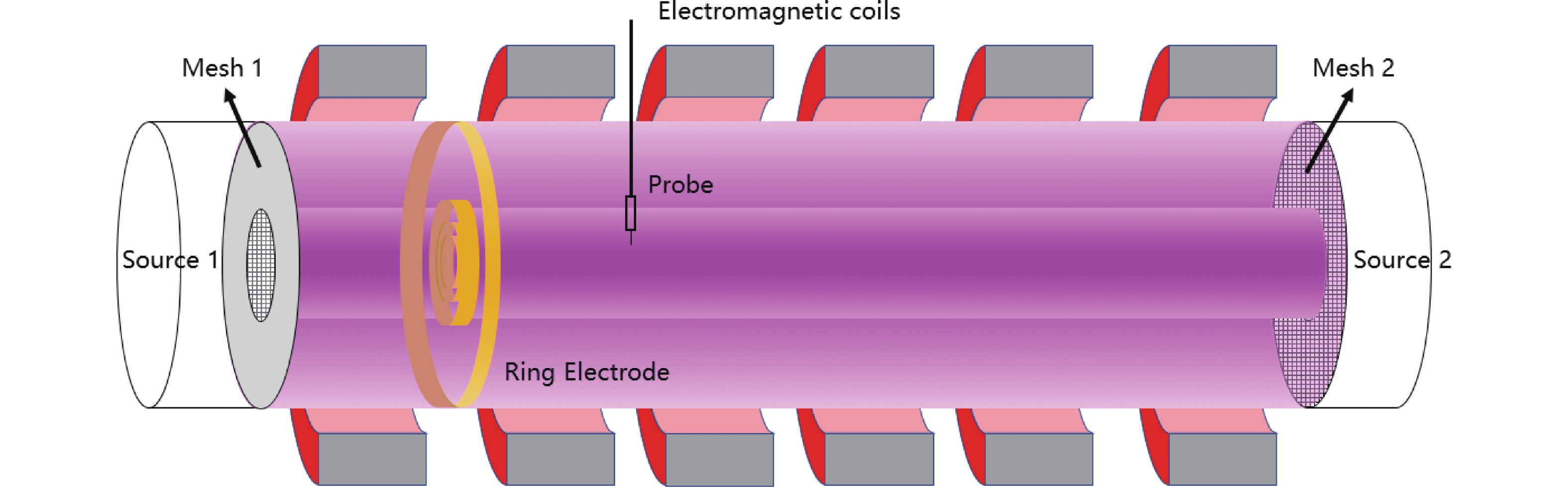
![]() Schematic of the plasma sources and two types of biasing electrodes applied to generate sheared E × B flow.
Schematic of the plasma sources and two types of biasing electrodes applied to generate sheared E × B flow.
-
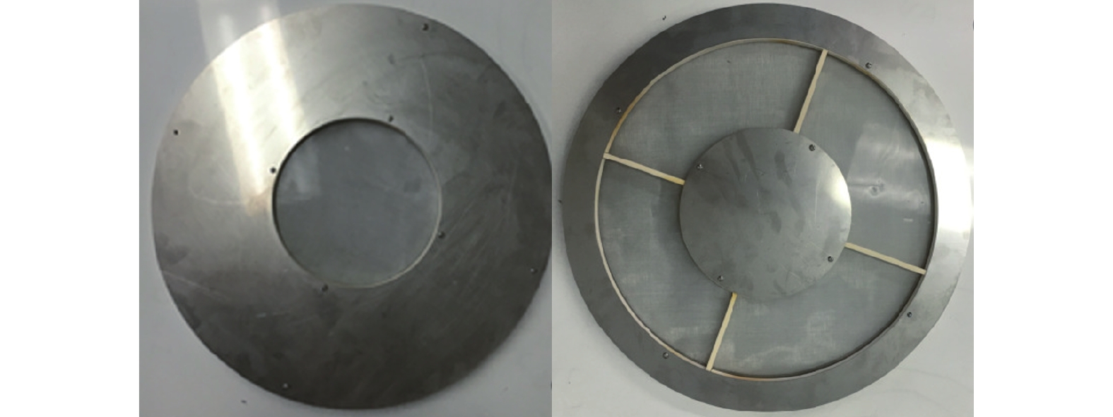
![]() Mesh 1 and Mesh 2 used to bias two plasma layers.
Mesh 1 and Mesh 2 used to bias two plasma layers.
-
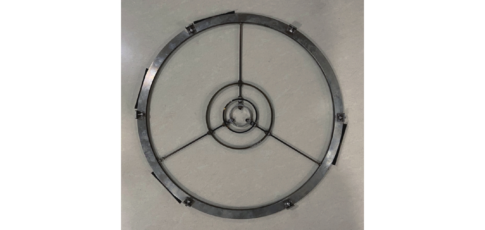
![]() Ring electrode designed to modulate the distribution of plasma potential.
Ring electrode designed to modulate the distribution of plasma potential.
-
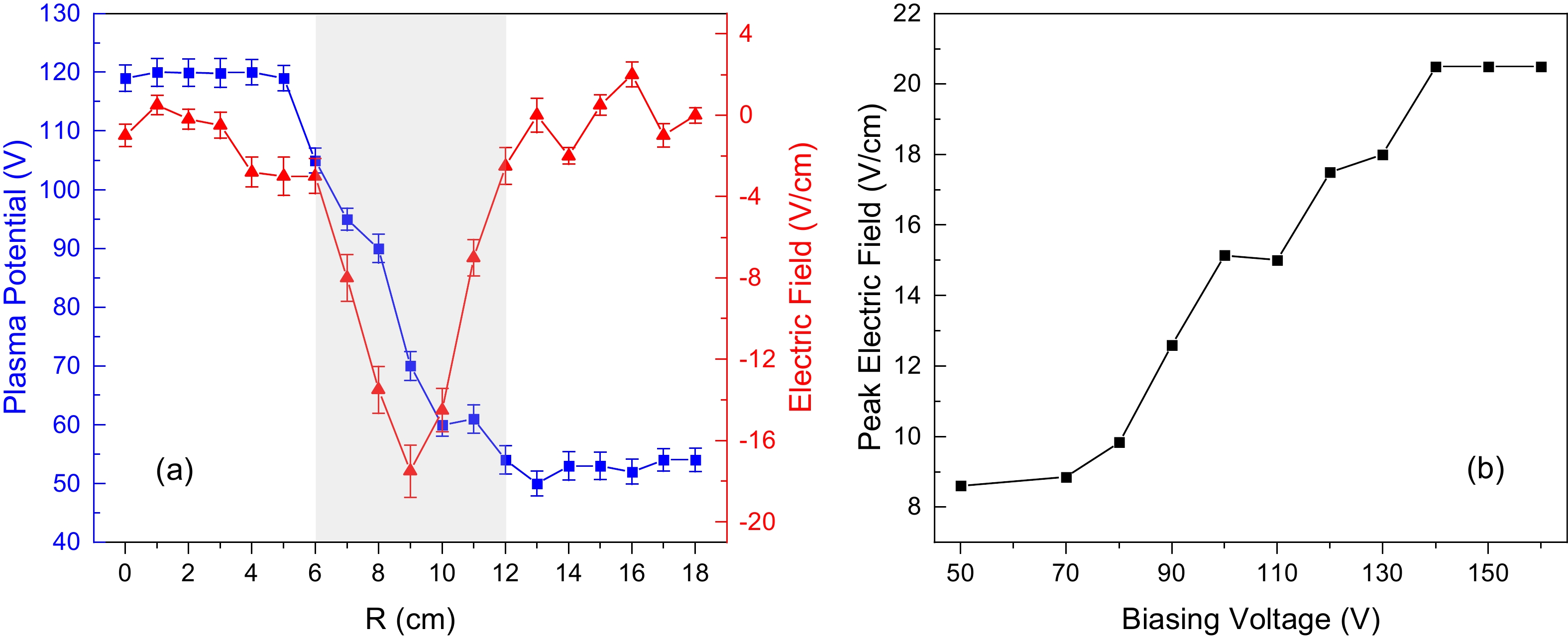
![]() (a) Radial profiles of the plasma potential and the electric field with Mesh 1 biased at
(a) Radial profiles of the plasma potential and the electric field with Mesh 1 biased at $120\;\mathrm{ }\mathrm{V}$ and Mesh 2 grounded. The grey shaded area denotes the sheared region. (b) The electric field peak value versus varying biasing voltage on Mesh 1. -
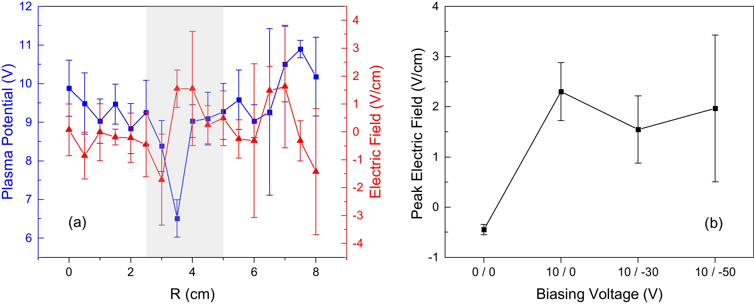
![]() (a) Radial profiles of the plasma potential and the electric field as the outer rings biased at 10 V and the inner ring biased at
(a) Radial profiles of the plasma potential and the electric field as the outer rings biased at 10 V and the inner ring biased at $-30\;\mathrm{V}$ . The grey shaded area denotes the sheared region. (b) The electric field peak value versus different biasing voltages. The horizontal axis is in the format of “bias on the outer ring / bias on the inner ring” while “$0\;\mathrm{V}$ ” refers to electrical floating or electrical insulation. The background magnetic field was fixed at$130\;\mathrm{G}$ for all these cases. -
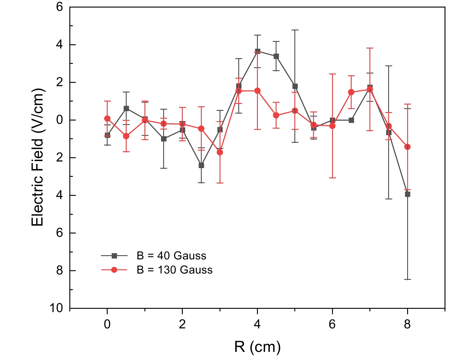
![]() Radial profiles of the electric field distribution under two different magnetic field strengths.
Radial profiles of the electric field distribution under two different magnetic field strengths.
-
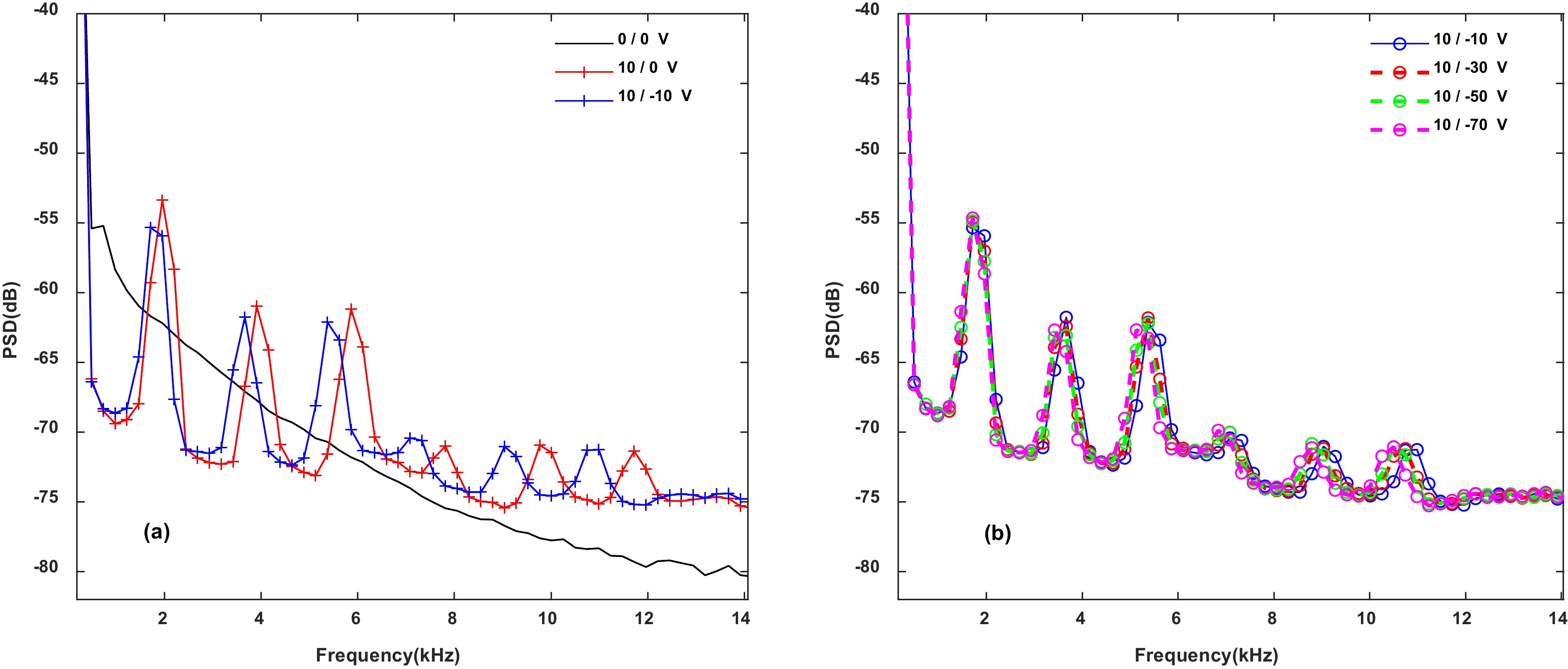
![]() PSD of potential fluctuation versus different biasing voltages on the ring electrodes. The legend is written in the format of “bias on the outer ring / bias on the inner ring” while “
PSD of potential fluctuation versus different biasing voltages on the ring electrodes. The legend is written in the format of “bias on the outer ring / bias on the inner ring” while “$0\;\mathrm{V}$ ” refers to electrical floating or electrical insulation. The magnetic field strength was fixed at$130\;\mathrm{G}$ , and the radial position was fixed at$4\;\mathrm{ }\mathrm{c}\mathrm{m}$ .